
1. Utangulizi
This manual provides instructions for the assembly, setup, operation, and maintenance of the Weytoll Signal Generator Kit. This device is a DIY (Do-It-Yourself) kit designed to generate various waveforms including sine, square, triangular, and sawtooth waves, with an adjustable frequency range from 1Hz to 20MHz.
As this is a DIY kit, user assembly is required. Please read all instructions carefully before beginning assembly or operation.
2. Taarifa za Usalama
Daima zingatia tahadhari zifuatazo za usalama:
- Hakikisha ugavi wa umeme ujazotage iko ndani ya safu maalum (9V hadi 15V DC).
- Usiendeshe kifaa kwenye mvua au damp masharti.
- Avoid touching exposed circuit components when the device is powered on.
- Use appropriate tools and follow proper soldering techniques during assembly to prevent damage to components or injury.
- Weka kifaa mbali na watoto.
3. Yaliyomo kwenye Kifurushi
Verify that all components listed below are present in your kit. If any parts are missing or damaged, please contact customer support.
- 1x Signal Generator PCB (Printed Circuit Board)
- 1x Acrylic Casing Set (Top and Bottom panels, screws)
- Electronic Components (Resistors, Capacitors, ICs, Potentiometers, Connectors, etc.)
- 1x Mwongozo wa Mtumiaji (hati hii)
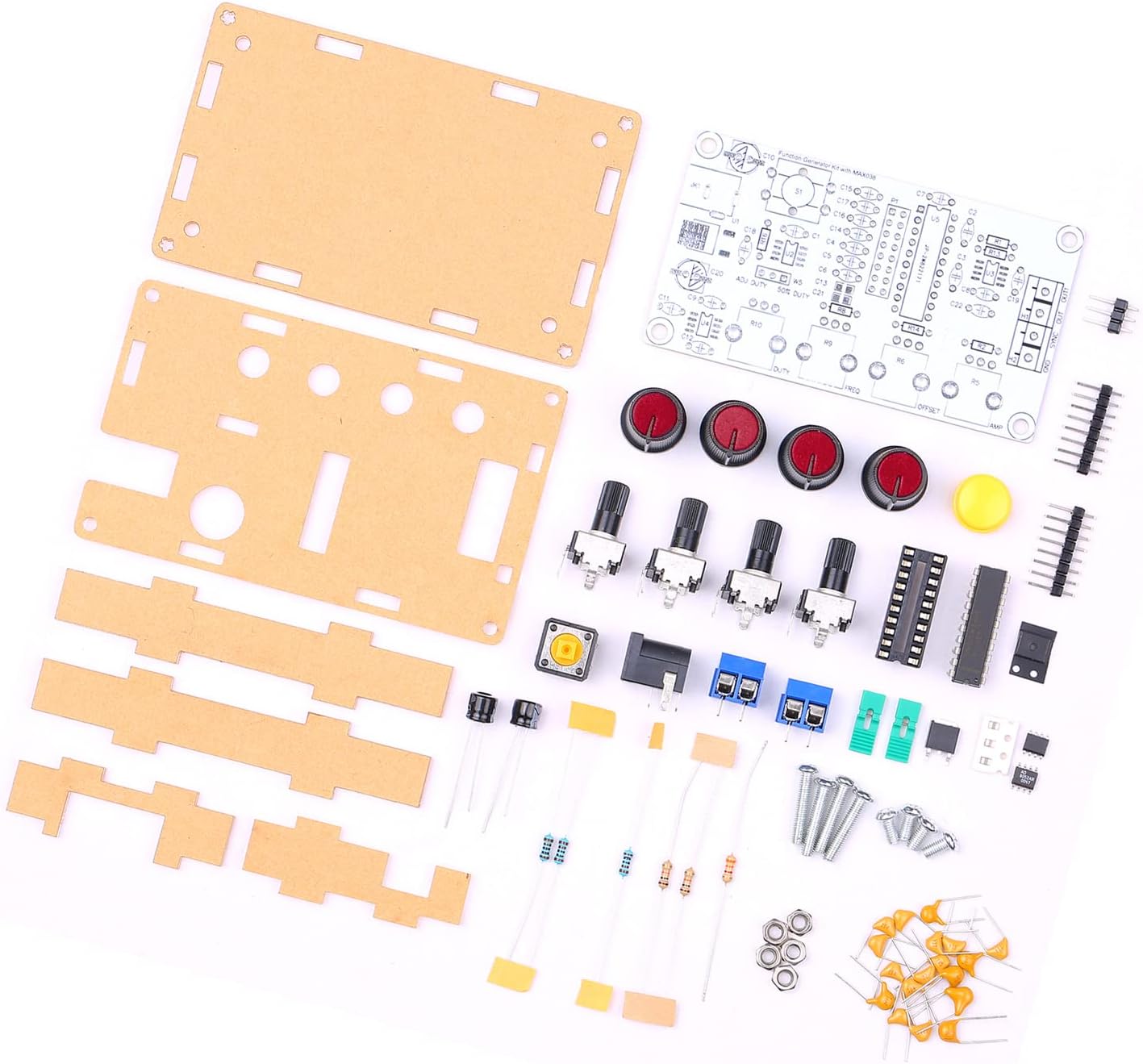
Figure 3.1: All components included in the Weytoll Signal Generator Kit.
4. Maagizo ya Mkutano
Assembly of this kit requires basic soldering skills and tools (soldering iron, solder, wire cutters, multimeter recommended). Follow the steps below carefully.
- Utambulisho wa vipengele: Before soldering, identify all components using the provided circuit diagram (if included, otherwise refer to component markings). Sort resistors by value, capacitors by type and value, and identify integrated circuits (ICs).
- Solder Smaller Components First: Begin by soldering the smallest components to the PCB, such as resistors and diodes, followed by capacitors, IC sockets (if using), and then the ICs themselves. Pay attention to polarity for diodes, electrolytic capacitors, and ICs.
- Install Larger Components: Solder the larger components like potentiometers, connectors (power jack, output terminals), and switches. Ensure they are flush with the PCB and correctly oriented.
- Verify Soldering: After all components are soldered, carefully inspect all solder joints for bridges, cold joints, or missing connections. Use a multimeter to check for continuity where appropriate.
- Assemble Acrylic Casing:
- Remove protective film from both sides of the acrylic panels.
- Attach the bottom acrylic panel to the PCB using the provided standoffs and screws.
- Align the top acrylic panel, ensuring all potentiometers, switches, and connectors fit through their respective openings. Secure with the remaining screws.
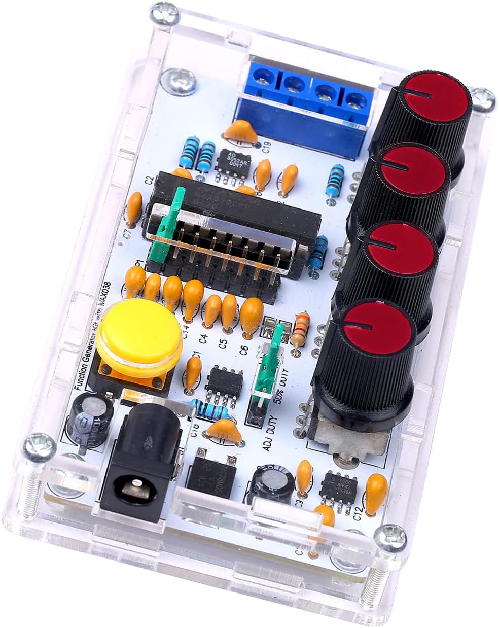
Figure 4.1: Fully assembled signal generator kit.
5. Kuweka
Once assembled, follow these steps to set up your signal generator:
- Muunganisho wa Nishati: Connect a DC power supply (9V to 15V) to the power input jack. Ensure correct polarity.
- Muunganisho wa Pato: Connect the signal output (OUT) to your desired measurement device (e.g., oscilloscope, frequency counter) using appropriate cables. The SYNC OUT provides a synchronization signal.
- Mipangilio ya awali: Before powering on, set all potentiometer knobs to their center positions or minimum values to avoid unexpected outputs.
6. Maagizo ya Uendeshaji
The Weytoll Signal Generator Kit allows for adjustment of frequency, duty cycle, DC offset, and amplitude. It can generate sine, square, triangular, and sawtooth waveforms.
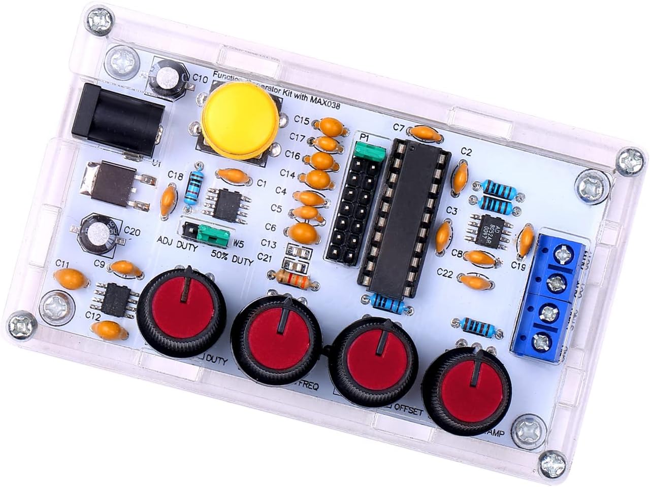
Figure 6.1: Control knobs for signal adjustment.
- Frequency Adjustment (FREQ): Use the FREQ knob to adjust the output frequency from 1Hz to 20MHz.
- Duty Cycle Adjustment (DUTY): Use the DUTY knob to adjust the duty cycle of square and sawtooth waves from 15% to 85%.
- DC Offset Adjustment (OFFSET): The OFFSET knob allows for adjusting the DC offset of the output signal from -5V to +5V.
- Amplitude Adjustment (AMP): Tumia AMP knob to adjust the peak-to-peak amplitude of the output signal from 0.1VPP to 9.5VPP (with a 9V operating voltage).
- Uteuzi wa Umbo la Mawimbi: The kit supports output of triangular, square, sine, and forward/reverse sawtooth waves. Refer to the PCB markings or a detailed circuit diagram for specific waveform selection points or switches, if present.
- Synchronization Output (SYNC OUT): This terminal provides a synchronization signal, useful for triggering oscilloscopes or other external devices.
7. Matengenezo
The Weytoll Signal Generator Kit requires minimal maintenance:
- Kusafisha: Weka kifaa kikiwa safi na bila vumbi. Tumia kitambaa laini na kikavu kwa ajili ya kusafisha. Usitumie visafishaji vya kioevu.
- Hifadhi: Hifadhi kifaa katika mazingira makavu na baridi wakati hakitumiki.
- Ukaguzi: Periodically inspect the connections and solder joints for any signs of wear or damage.
8. Utatuzi wa shida
If you encounter issues with your signal generator, refer to the following troubleshooting guide:
| Tatizo | Sababu inayowezekana | Suluhisho |
|---|---|---|
| Hakuna ishara ya kutoa |
|
|
| Incorrect frequency/waveform |
|
|
| Umbo la wimbi lililopotoshwa |
|
|
Tatizo likiendelea baada ya kujaribu suluhu hizi, tafadhali wasiliana na usaidizi kwa wateja.
9. Vipimo
The following are the technical specifications for the Weytoll Signal Generator Kit:
| Kigezo | Thamani |
|---|---|
| Nambari ya Mfano | XXI0262789081113FJ |
| Nyenzo | PCB + Acrylic |
| Frequency Adjustment Range | 1Hz ~ 20MHz |
| Duty Cycle Adjustment Range | 15% ~ 85% |
| Low Loss True Sine Wave | 0.75% |
| Triangular Wave Output Linearity | 0.1% |
| Low Impedance Output Buffer | 0.1Ω |
| Adjustable DC Offset | -5V ~ 5V |
| Toleo Linaloweza Kurekebishwa Ampelimu | 0.1VPP ~ 9.5VPP (with 9V operating voltage) |
| Uendeshaji wa Ugavi wa Nguvu Voltage | 9V ~ 15V DC |
| Joto Drift | 200 ppm/°C |
| Vipimo vya Kipengee (L x W x H) | 99 x 59 x 32 mm (inchi 3.90 x 2.32 x 1.26) |
| Uzito wa Kipengee | 82 g |
| Vipimo vya Kifurushi | Sentimita 17.78 x 15.24 x 1.78 (inchi 7 x 6 x 0.7) |
| Uzito wa Kifurushi | 89 g |

Figure 9.1: Physical dimensions of the signal generator.
10. Udhamini na Msaada
Warranty information for the Weytoll Signal Generator Kit is not explicitly provided in the product details. Please refer to your purchase documentation or contact the seller directly for warranty terms and conditions.
For technical support or inquiries regarding assembly and operation, please contact Weytoll customer service through the retailer's platform or their official webtovuti, ikiwa inapatikana.